Introduction
The Inner Light scale model lighting system is the most advanced solution currently available for lighting models. Whether you are a professional model builder or home enthusiast, and regardless of the type of model you are building, the Inner Light solution represents the cutting edge of model lighting technology.
The solution consists of a tiny computer controller, together with one or more LED (Light Emitting Diode) chips connected together in a chain. Each individual LED can then be controlled - its color, brightness, and effect can be dynamically altered, either with physical buttons, or via a WiFi network.
Computer Controller
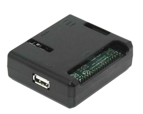 |
The Computer Controller is the intelligence behind the system. It connects to the first LED in the chain, and issues commands to
control all the LEDs, individually if required. |
LED Lights
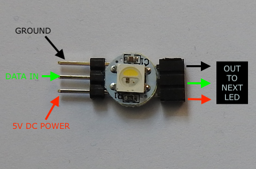
Each LED unit contains a Red, Blue, Green and White micro LED, which allows over 16.5 million color combinations. At maximum brightness each LED can theoretically draw 60mA (20mA max for a single color eg red or dedicated white). The LED chips require 5V DC, and are connected in a daisy chain - with a Data In and Data Out connection:
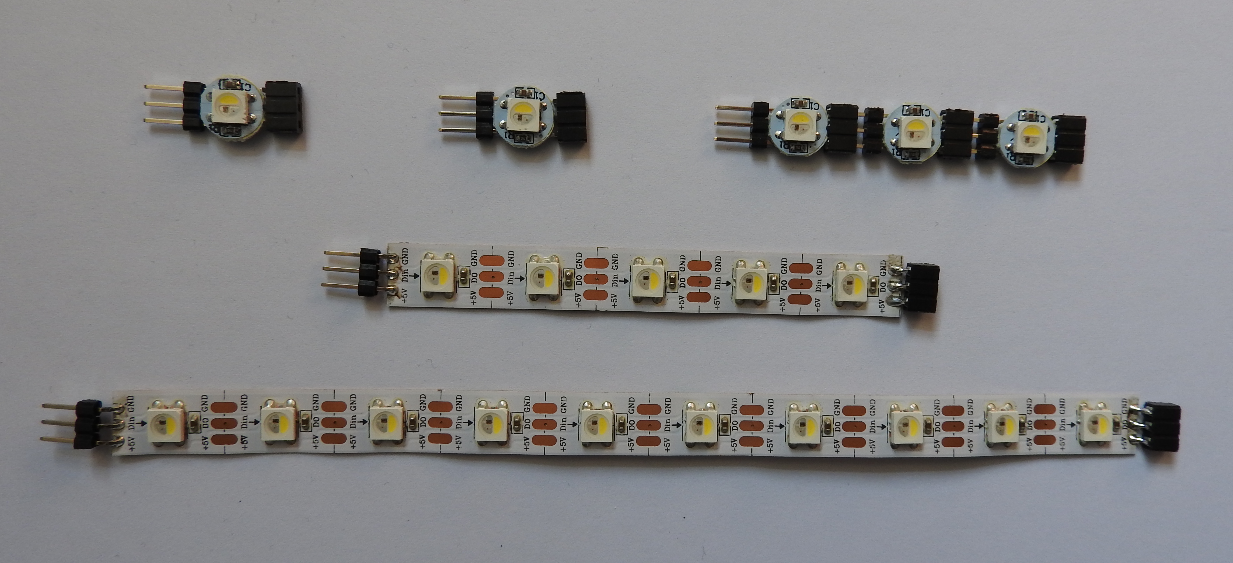
The LED units are available in single units (requires soldering), single interlocking (no soldering required) or strip versions, depending on your requirements.
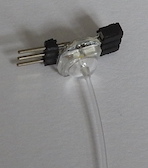
You can also connect a lens cover to the LED units in order to run fibre optic cable for small spaces:
Quick Start Guide
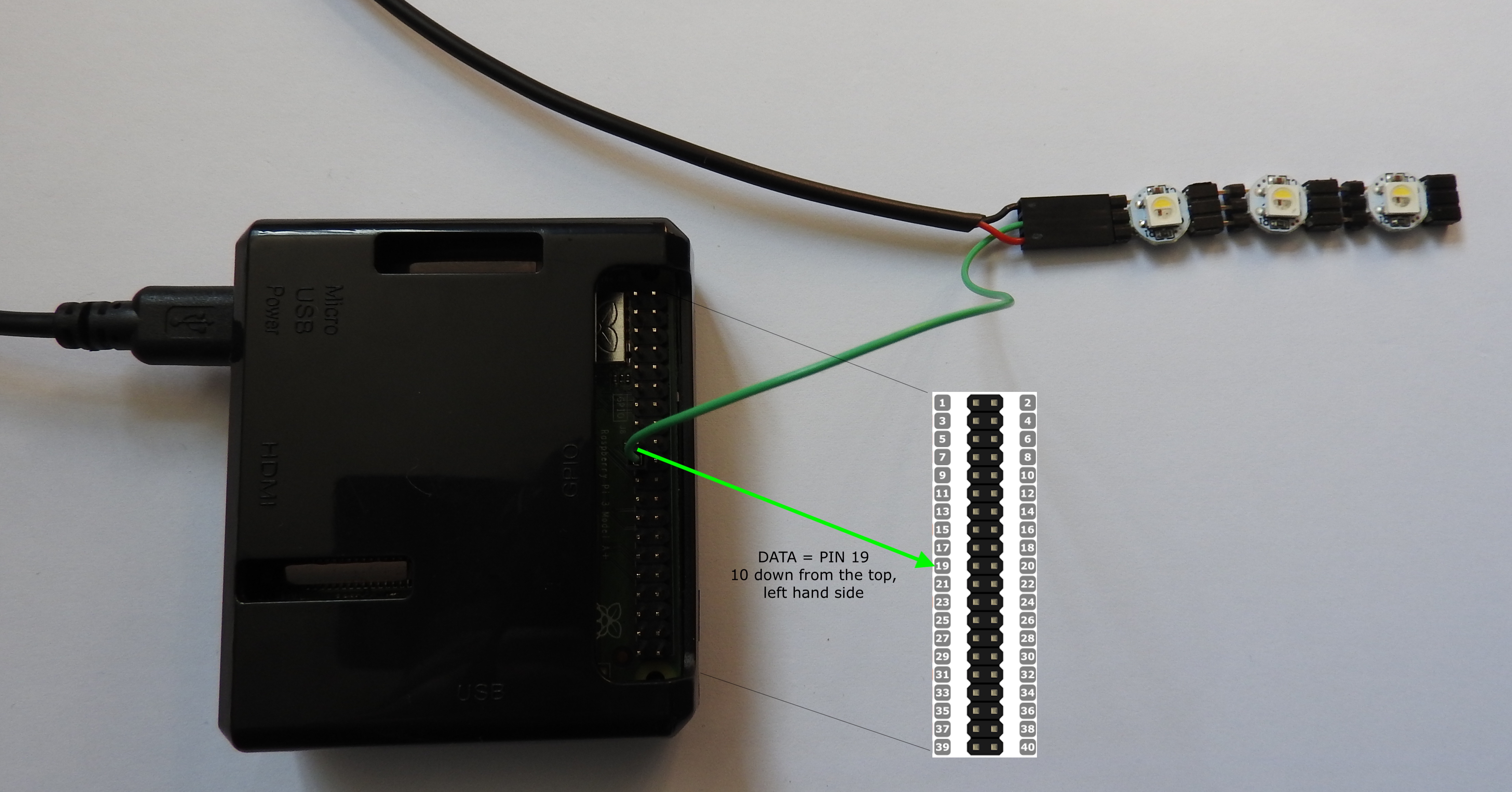
First, connect the single wire LED data cable from the USB lead to the Computer Controller data output pin. Connect to pin 19 as shown, which is the 10th pin down from the top left. DO NOT CONNECT TO ANY OTHER PIN!! Pin headers will surround the correct pin to assist in locating it.
Next, connect the power/data cable to the first LED as shown below. IMPORTANT: the red cable goes to the 5V connection, bottom left of the LED chip as shown.
Finally, connect the micro usb power connection to the Computer Controller, top left shown below:
When first purchased, the Computer Controller will power up and start broadcasting its own WiFi network called 'Inner Light' which you can connect to using your computer, with
the password 'innerlight' (lowercase, all one word). Once connected to the 'Inner Light' network, you can then connect to the main web interface by browsing to the following address:
http://192.168.1.100
or
http://il.local
You can also use https in place of http for a more secure connection - note depending on your browser you may receive a https certificate warning.
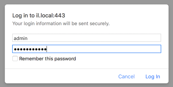
You will then need to log in using the username: 'admin' and the web interface password 'password'.
Once you have logged in to the web inteface, you can configure the number of LEDs which you wish to control, the maximum brightness, and begin to configure the elements of the solution:
LED Groups
These are the groups of LEDs that you want to individually control. A group can consist of one or more LEDs, eg '1' or '1,2,3,4,5' or '1-5' or '1,3,5-8,13' etc
LED Effects
These are the effects you wish to apply to one or more LED groups, eg solid red, or flashing green.
Scenes
This is where you link LED Groups with LED Effects to produce an overall lighting scene, with optional sound and video effects. For example you may want to apply an effect called 'flash white' to the LED Group called 'navigation lights'
Powering Down
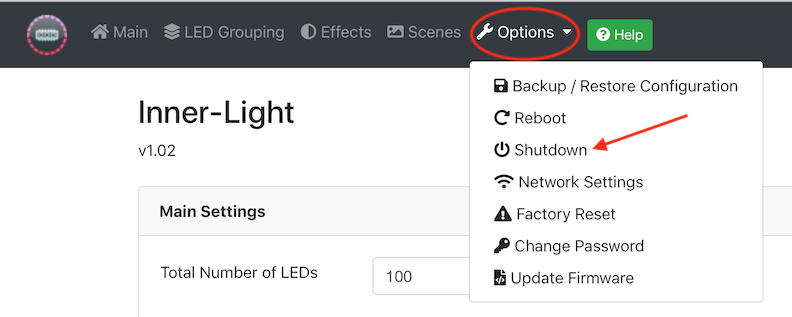
When you are finished with the controller, always shut it down using the web interface menu option or physical control button, and wait 30 seconds BEFORE disconnecting power. Failure to do so may result in damage to the operating system.
WiFi Network
The computer controller has a built in 2.4GHz and 5GHz IEEE 802.11.b/g/n/ac wireless LAN interface. This means that it can connect to your own WiFi network or be configured and controlled independently using its own WiFi network which you can connect your computer to.
Out of the box, the controller will broadcast its own WiFi network called 'Inner Light'. You can connect to this using the default password 'innerlight'.
You can then connect to the web server configuration page, at http://192.168.1.100 - and log in with username 'admin' password 'password'.
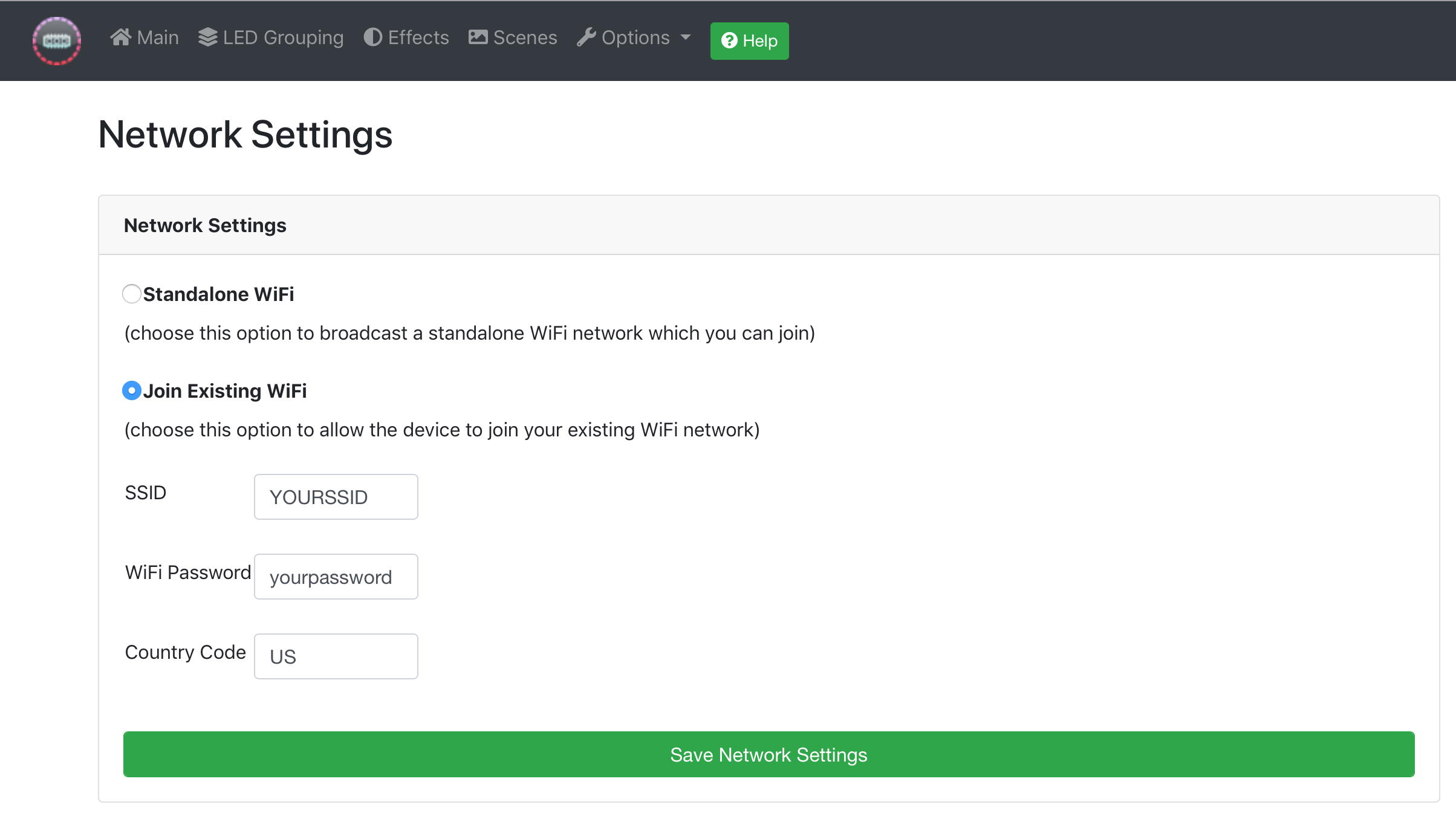
You can change the WiFi password, and/or the SSID name from the Network configuation page of the web server.
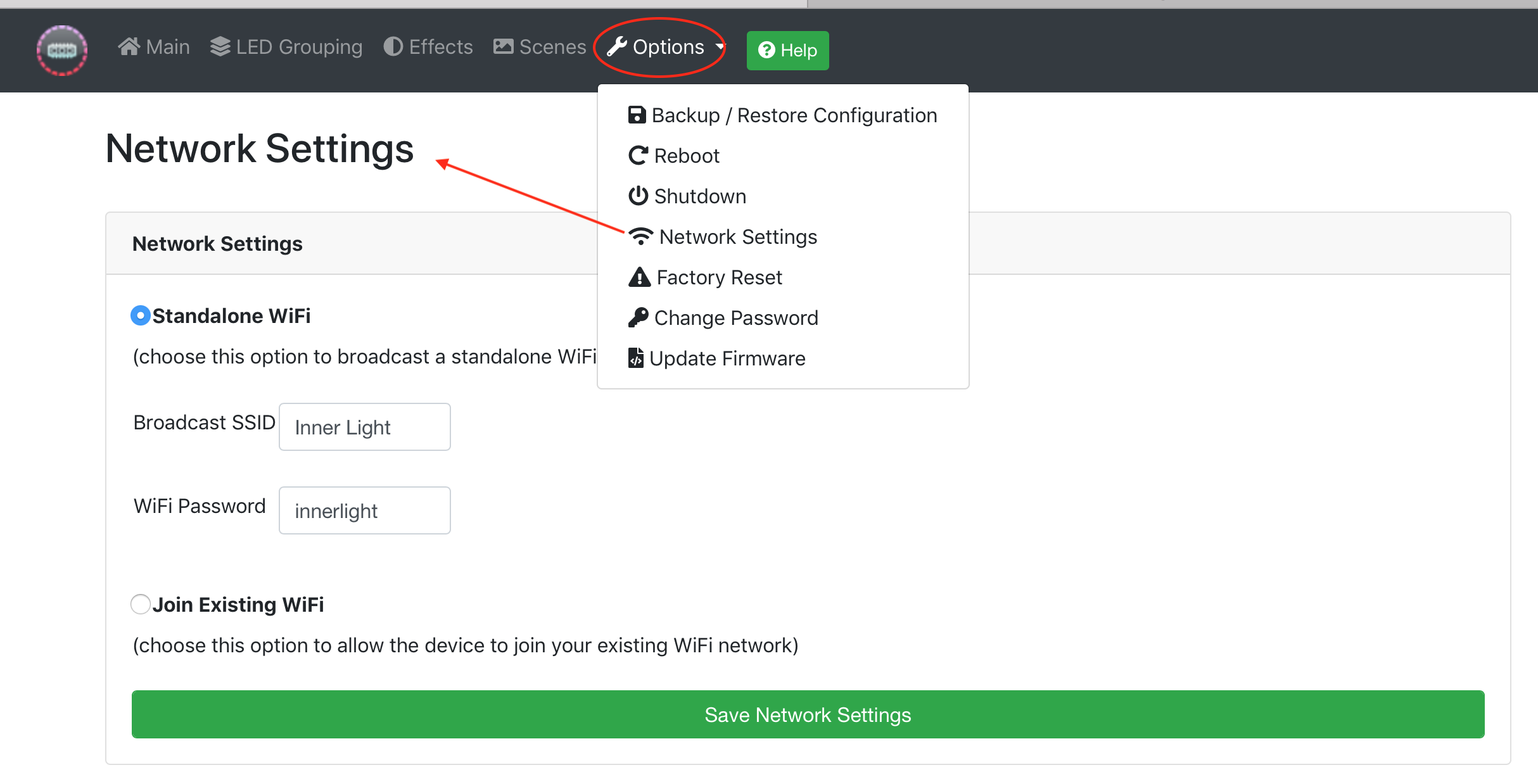
You also have the option of allowing the controller to connect to your own existing WiFi network by selecting the option on the web interface and entering your network details.
WARNING - if you enter these details incorrectly, you will need to factory reset the unit - please refer to the support section.
If you connect to your own WiFi network, the controller will be given a DHCP assigned address by your network router. You should also be able to access the unit at the address given by the router,
or at http://il.local
LED Groups
These are the groups of LEDs that you want to individually control. A group can consist of one or more LEDs. You can create as many groups as you wish, and the same LEDs can be listed in multiple groups if needed.
Enter the LED numbers, starting at 1, separated by commas. To include a range, use the - symbol, eg 5-10 would include LEDs 5,6,7,8,9 and 10.
You can choose to enter either the LEDs to include, or the LEDs to exclude - for example to affect all LEDs except for specific LEDs, choose this option.
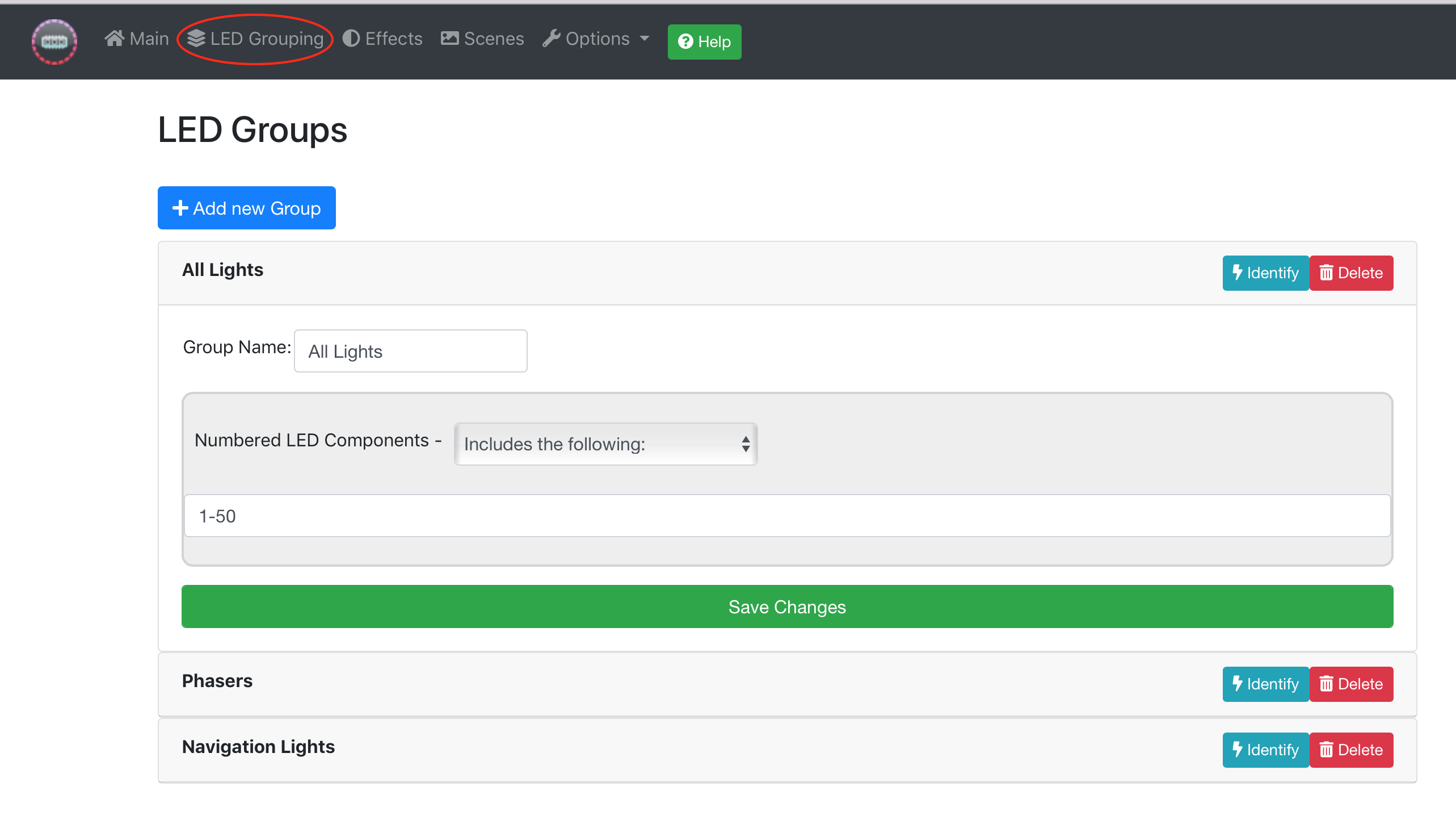
You should create a group for each section of lighting that you want to control.
LED Effects
An LED effect is a description of what you want your lights to do. An example would be flashing red, or fading from one color to another, or simply to statically emit a particular color.
You can create as many effects as you wish to achieve your desired result. LED effects themselves are independent of specific LEDs at this stage - you will assign effects to your LED groups in the Scenes section.
Each LED effect should be given a unique and meaningful name, eg 'Flash Green'
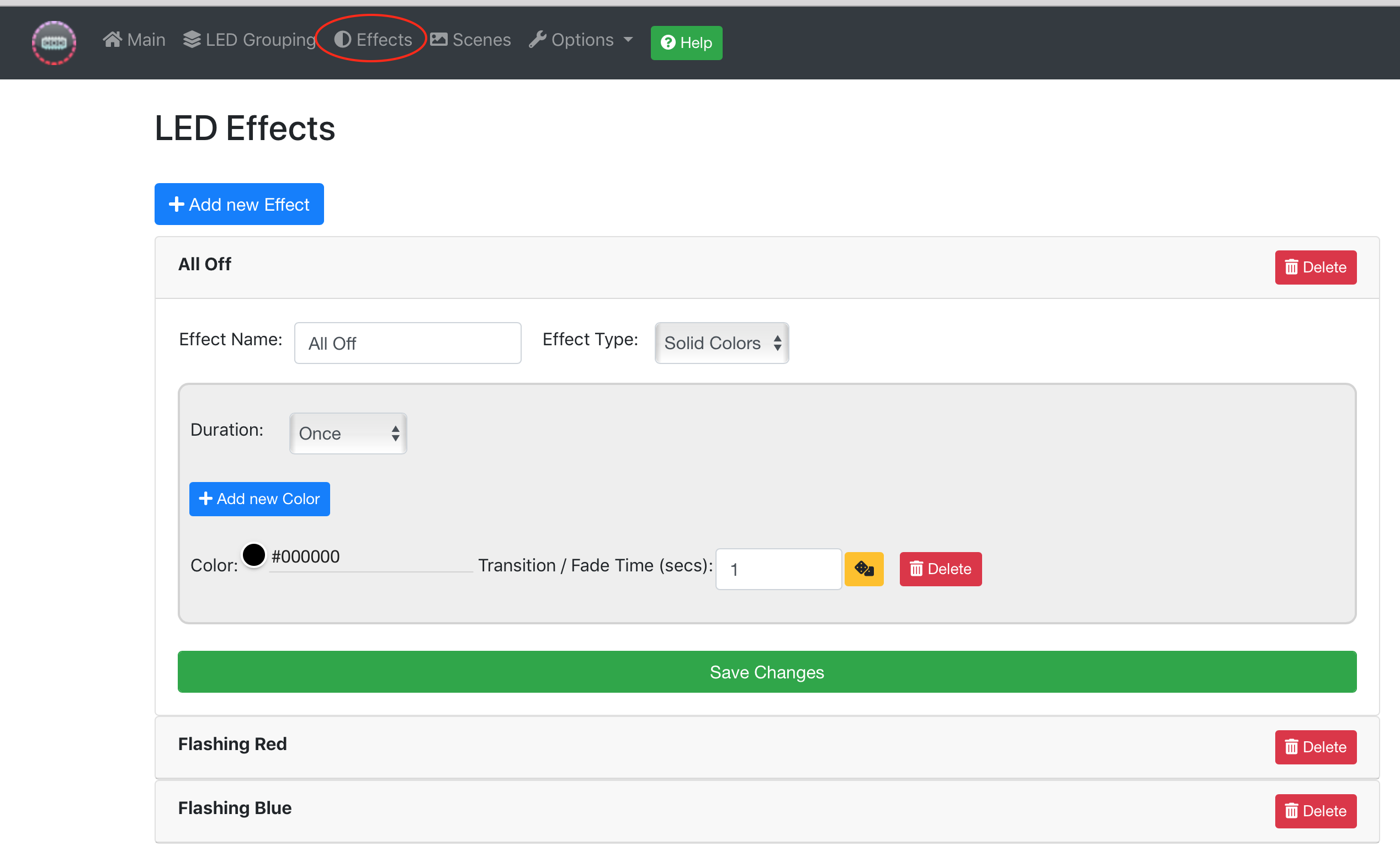
Solid LED Effect
This is the most basic LED effect, and lets you choose one or more colors to display. If you add more than one color, then each color will be displayed in sequence.
The transition / fade time is the time that will be taken to alter the LEDs from the color that they currently are, to the selected color, before moving on to the next color, if there is one.
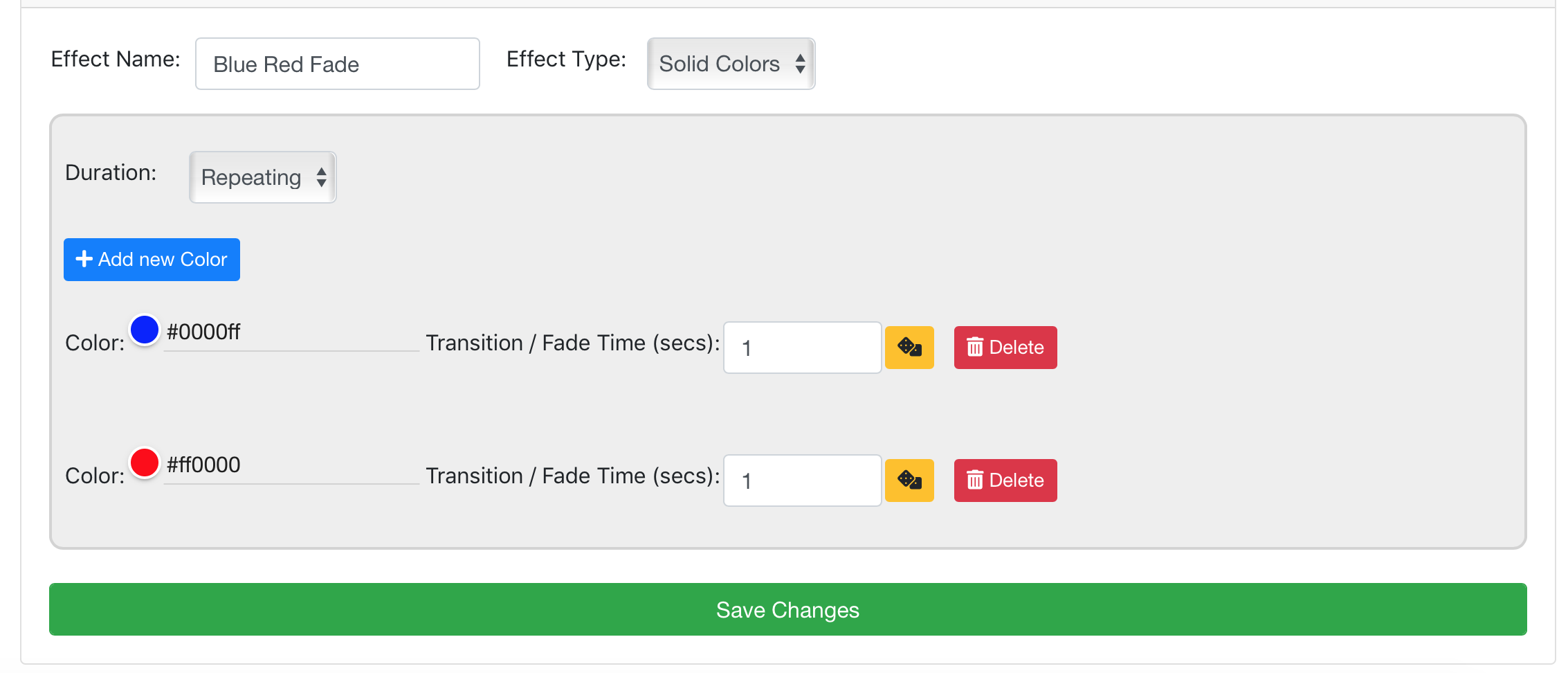
The duration parameter determines whether the cylce of colors will repeat indefintely, or just once. If you wish for this value to be a random parameter between 2 values, use the 'dice' button, or
enter the minimum and maximum possible values with a - character, eg 1.0-5.0 will result in a random fade time between 1 and 5 seconds.
Flashing LED Effect
This will cause the LEDs to flash the selected color. You decide for how long the LEDs should flash (the flash time), how long they should go back to their original color (the rest time), and how many times they should flash (number of flashes). If they are to flash more than once, then you can determine the amount of time between each flash cycle.
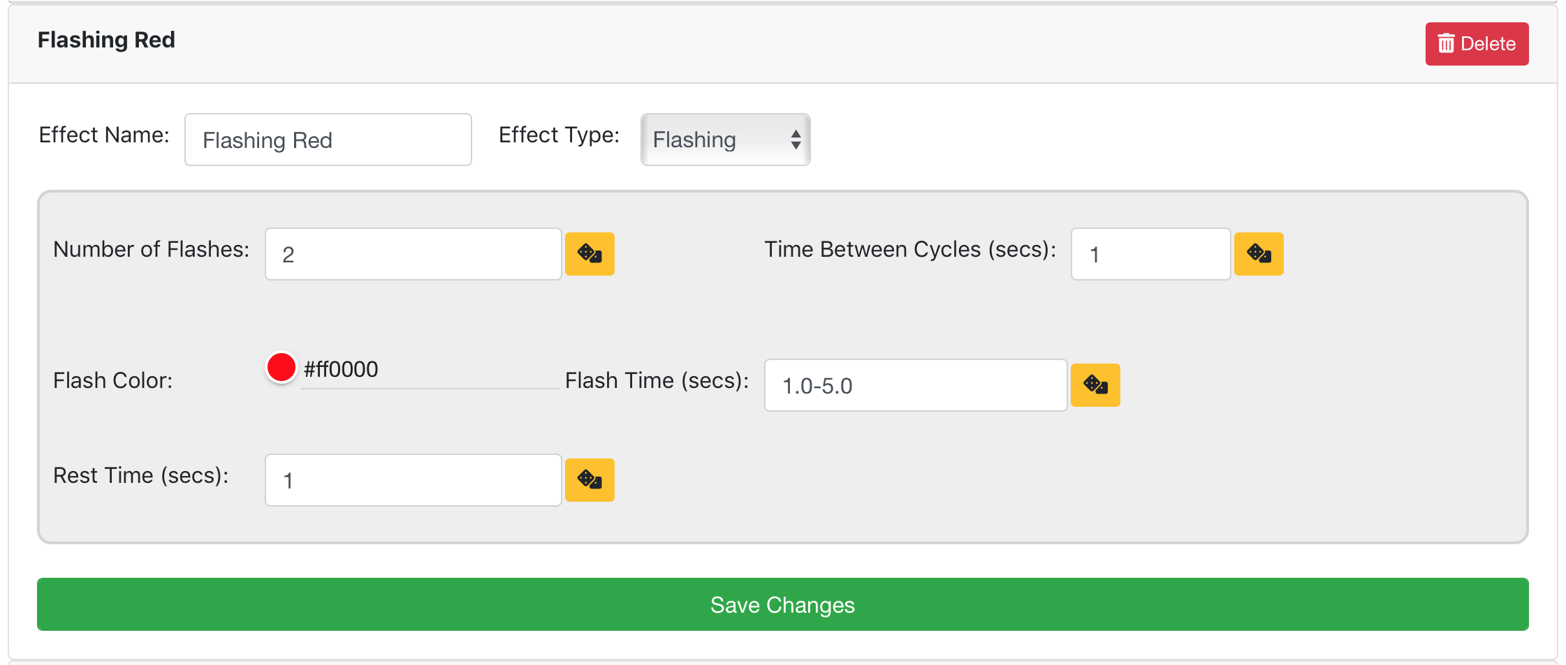
All of the timing parameters can make use of the random function, using the 'dice' button or entering minimum and maximum values with a - character, eg 1-4
would choose a random value between 1 and 4
Chase LED Effect
This effect causes each LED to illuminate sequencially from one end of the LED group to the other. The direction parameter determines where the LED trail begins and ends, and the duration parameter determines whether the sequence should repeat indefinitely.
The chase speed determines the time between each LED illumination. The tail parameter determines how 'long' the LED illumination sequence should be. The chase and background colors determine the colors to use.
If 'converge on LED' direction parameter is selected, the LEDs will illuminate at each end of the LED group, and gradually move towards the target LED position. Upon reaching the target LED position, you can choose the target LED color, and the amount of time it will dwell on that color before returning to the background color.
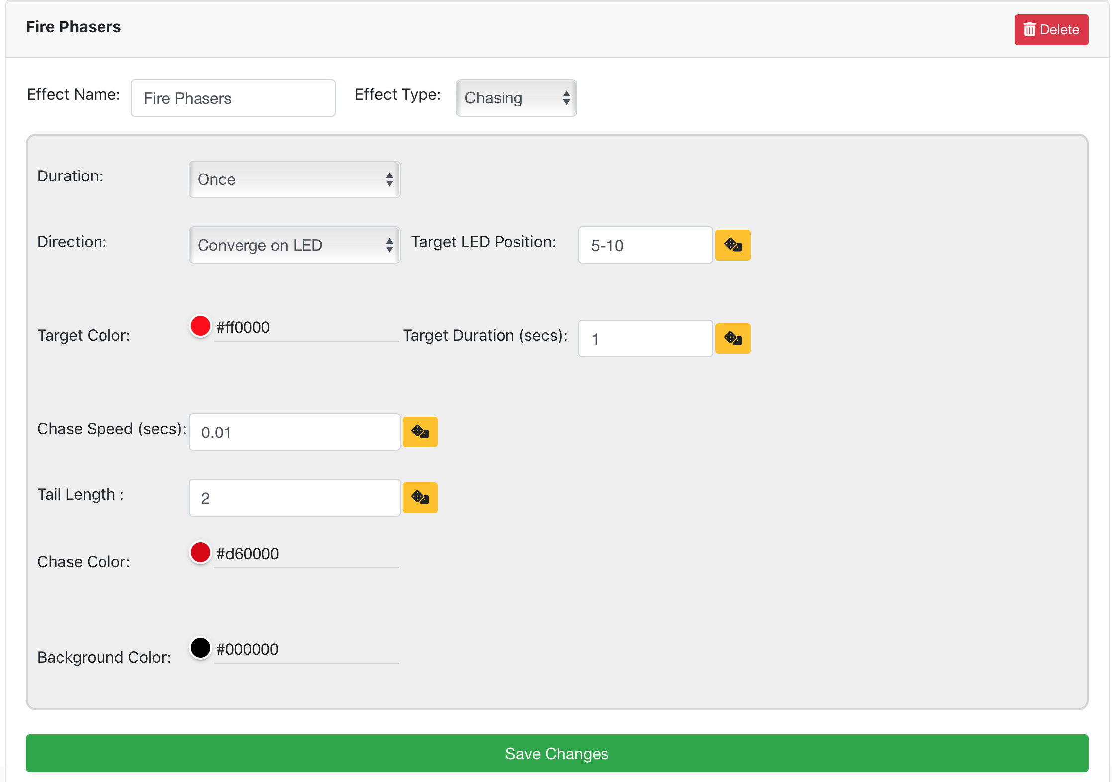
All of the timing and position parameters can make use of the random function, using the 'dice' button or entering minimum and maximum values with a - character, eg 1-4
would choose a random value between 1 and 4
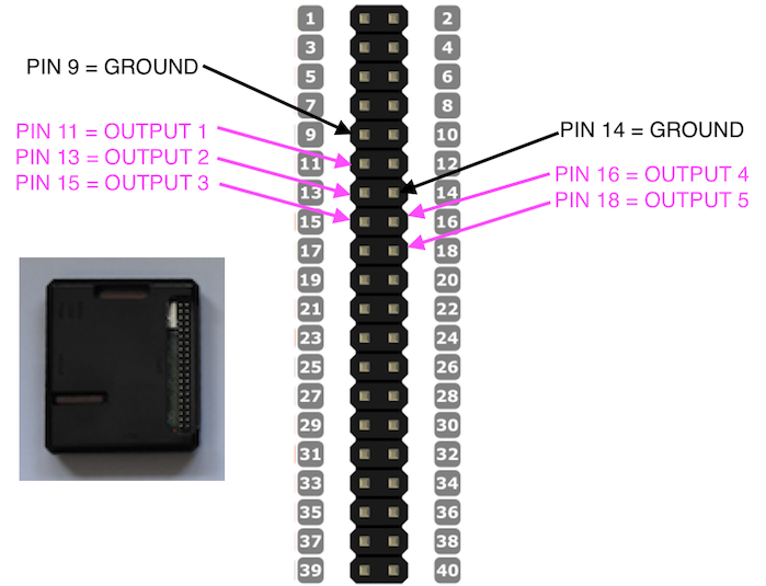
3.3V Controller Outputs
There are 5 output pins available on the pro controller which can be set to 0V (off) or +3.3V (On) with a command. Each output pin can deliver max 16mA, with 50mA total across all outputs.
These output pins can be used (via a 3.3V relay if necessary) to control equipment which requires an On or Off state, eg a relay, motor, standard LED, laser module, or other device.
You can include the state of the output pins when you activate a scene:
You can connect the output pins as follows:
IO Expansion Board
You can use 1 or more IO expansion boards, which allow you to control standard LEDs using 6 x controllable outputs. LED dimming is supported.
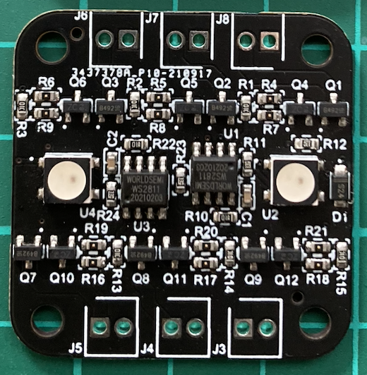
The board uses the same protocol as WS2811 / SK6815 addressable LEDs. 2 On board RGB LEDs are also incuded, which can be used with the fibre optic connectors if required. Multiple boards can be daisy chained together, or inserted anywhere on the addressable LED data line. The board takes up either 4 x RGB LED slots, or 3 x RGBW slots - it is compatible with either type of LED system. 500mA max per output.
The board are connected in the same way as the addressable LEDs - taking power & data in, and connecting data out to the next expansion board or LEDs. You then take +5V and ground (LEDx) from each output to control standard LEDs.
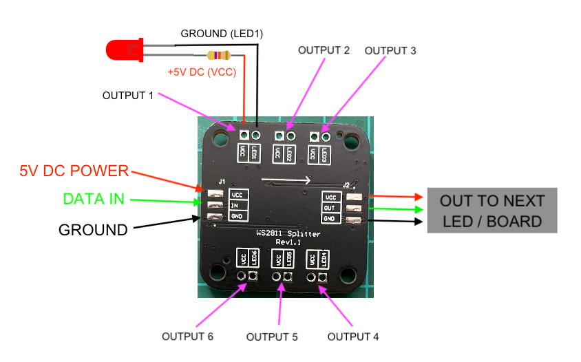
You control the board outputs as part of a scene - specifying the board 'address', output number (1-6) and required level (0-100%). The board address is similar to the other LED addresses, ie their position on the data line, eg if the board was connected to the data out of LED 10, then the board address would be 11, then the next LED/Board address would either be 15 or 14 depending on RGB/RGBW mode).
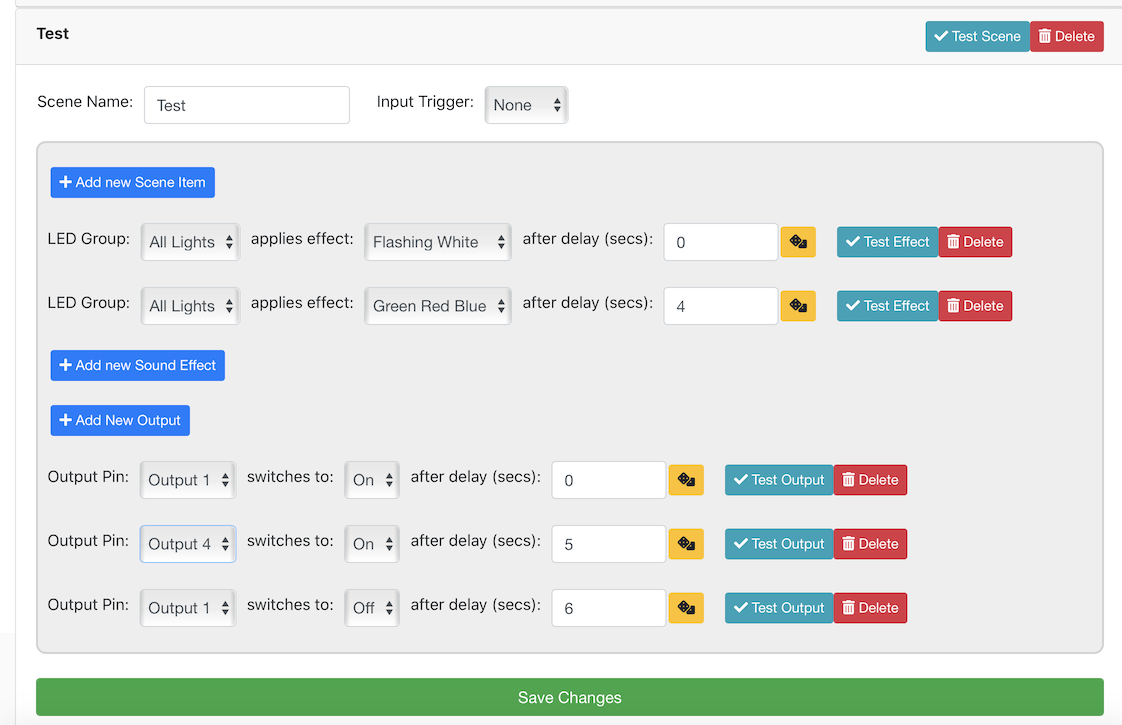
Scenes
Scenes are a way of linking LED Groups with LED Effects, and also optionally including sound effects and switching output devices. You can create as many scenes as you wish. Each scene can include zero or more lighting effects, and zero or more sound effects.
Each lighting or sound element can be delayed by an amount of time, if desired. The time can be random by using the 'dice' button, or entering minimum and maximum parameters separated by a - symbol, eg 1.0-5.0
It is perfectly valid for many lighting effects and sound files to be simultaneously playing at the same time - though any given LED can only be part of a single lighting effect at any one time, which would be the last effect applied to that particular LED.
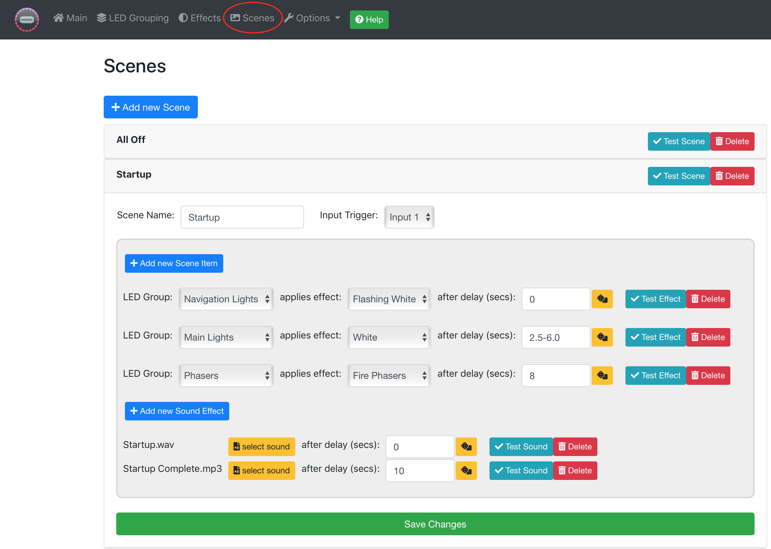
You can test the scenes, sound effects or outputs using the 'Test' buttons, and delete any unwanted elements using the 'Delete' button.
You may also assign a physical button to a particular scene using the 'Input Trigger' parameter, please refer to the Control Options - Physical Buttons section.
Physical Buttons
If you wish, you can connect physical buttons to the computer controller in order to trigger scenes, and also to shutdown and startup the controller.
You must use a basic contact button, which joins 2 connections together to trigger the event. One side of the button connection should be a ground connection,
(you can use any of the ground connections shown) and the other should be the appropriate pin for the function: startup, shutdown, or inputs 1-8.
When the button is pressed, the pin is connected to ground, and the function is triggered.

Note pin 40 (Shutdown) also serves as a factory reset option. if the unit is powered up whilst the button is pressed
(ie whilst pin 40 is connected to one of the ground connections), the unit will default to factory settings.
Network Commands
You can send network commands from any 3rd party system to initiate scenes. The commands are HTTP/HTTPS GET requests. Here is an example command which activates a scene called 'Startup':
https://admin:password@192.168.1.100/api/scenes/Startup/apply
Replace 'password' with your web password. Replace 'Startup' with the name of your scene. If your scene contains a space, use %20 instead of the space character.
Replace '192.168.1.100' with the IP address of your unit, if it is connected to your network (you can also use IL.local in place of the IP address, depending on your computer / network). If sending the command from an external source, eg IFTTT.com, use
the external IP address of your network, and ensure that port 443 TCP is forwarded through your router.
You can test these commands by simply entering the URL into a browser which is able to reach the IP address specified.
Saving and Restoring Configurations
By connecting the included USB disk drive to the computer controller, it is possible to save the current configuration as a restore point. First, select the 'Backup / Restore Configuration' menu option:
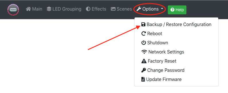
To backup your configuration, enter a name for the backup and click 'Backup Now'. Note this will only work if the USB drive is connected.
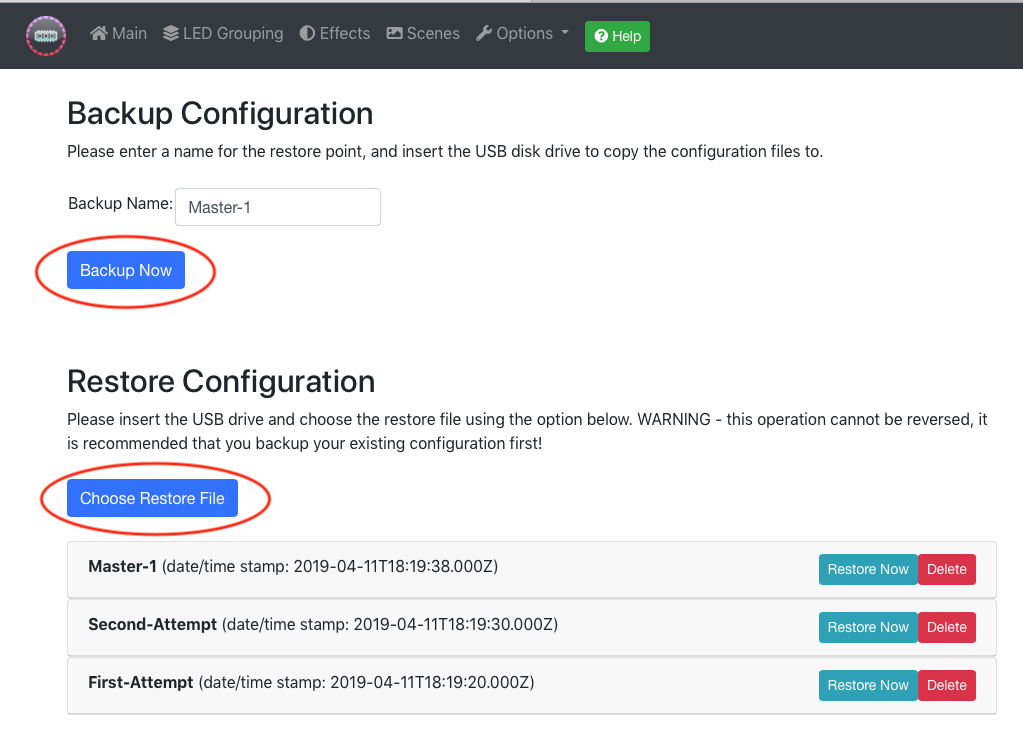
To restore the configuration from a previously saved backup, select 'Choose Restore File'. This will list the restore files on the USB drive, and will allow
you to remove them, or restore them. Note restoring to a previously saved configuration will delete the current configuration.
Support
For answers to any questions, or suggestions for improvement please contact support@scalectronics.com
Firmware Updates
Firmware updates add functionality to the solution, and will be issued periodically. The version of firmware on the unit is displayed on the main web configuration page.
To update the firmware, download the latest firmware update file from http://www.scalectronics.com or by emailing support@scalectronics.com and save it to the USB disk. Connect the USB disk to the computer controller and select 'Update Firmware' from the Options menu.
Factory Reset
There are several ways to perform a factory reset of the pro controller. Note this will delete all your settings, and reset the unit to the state it was when purchased.
1. The recommended way is via the web interface, by selecting the 'Factory Reset' option from the Options menu
or:
2. If you are unable to get to the web menu (eg you have forgotten your password), connect pin 40 to Ground pin 39 (the bottom 2 pins) in order to shut the unit down, then wait 30 seconds and disconnect power momentarily, and then reconnect power with the pins
still connected together to perform a reset of the WiFi and web password. The process should take around 30 seconds, after which the unit should broadcast the 'Inner Light' standalone WiFi network and be back to original settings. You can then disconnect pins 39/40.
Rewriting the SD card
If the above fails or cannot be attempted, you can rewrite the SD card which runs the Pro Controller operating system. To do this, you will need some software which writes disk images to SD cards, such as Win32DiskImager.
A copy of Win32DiskImager for Windows can be downloaded by clicking HERE
In addition to the image writing software, you will also need the disk image itself, please email in to request the latest link.
Once you have the image file (large file ~4GB), you can remove the SD card from the Pro Controller, insert it into your computer (using a micro-SD adapter if required) and use the disk writing software to write the disk image to the SD card.
When complete, eject & remove the SD card from your computer & re-insert into the Pro Controller & power it back up. When you connect to the web interface for the first time, there will be an 'invalid licence' error message with a long number - email that
number into support and a replacement licence will be issued (please make a note of this in case it is needed in the future). You can then enter the licence at http://192.168.1.100/#!/licence
Troubleshooting
The following may help when attempting to troubleshoot problems with the system, for example if lights are flashing randomly, or colors are not correct. One quick test is to reduce
the maximum brightness setting significantly to see if that solves the issue - if it does, then it points to a power problem:
Power Requirements
Each individual LED can theorectically draw up to 60mA, depending on the color chosen, and the global maximum brightness setting. The base controller also draws power (typically 0.5A) - so it is
important to note the maximum power requirements for a given deployment, and to ensure sufficient power is being supplied, and the thickness of the cable is appropriate to carry the current required for all the LEDs connected to it.
If there is insufficient power, then as more LEDs are lit, others may not light up at all, or may display incorrect colors.
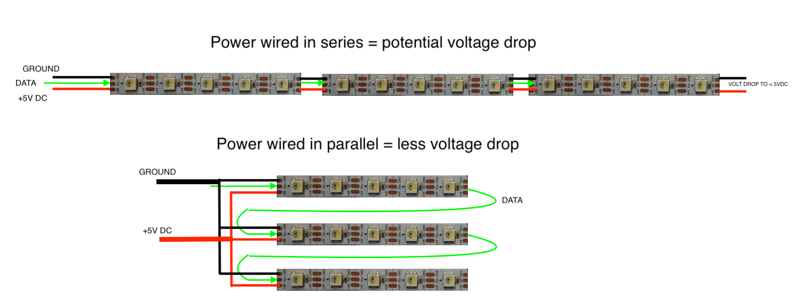
Voltage Drop
The LEDs require 5V DC to operate. Voltage drop can occur when using long, and/or thin runs of cable, where the voltage towards the end of the cable run is less than at the start. LEDs which are not receiving 5V due to voltage drop will experience similar issues to insufficient power -
incorrect colors, flashing, or no light whatsoever. The solution to voltage drop is to a) use thicker cable and/or b) reduce the length of the cable being used.
The following graphic shows a suitable wiring plan for large numbers of LEDs, where the power connections are made in parallel, with thicker cables nearer the power supply. Note the data in / data out connection must form a daisy chain from the first LED to the last, however the power connections do not need to be daisy chained, they can be wired in parallel. Indeed, separate power supplies can be used for different sections of LEDs if required, as long as the negative connections are common.
Wireless Interference
It has been observed that some installations of the system, particularly those with long runs of cable, experience interference on the data line caused by nearby wireless signals - where the cable effectively acts as a wireless antenna. This can result in random flashing of certain lights etc. It is good practice to use one of the circular LED chips at the very start of the data line, near to the base controller, and also use one at the very end of the data chain. The circular LED chips have resistors built in to the data line which help with the interference, whereas the 5mm or Nano LEDs for example, do not.